The Benefits of Automated Ultrasonic Testing using Advanced Gain Correction Map Technique (GCM)
Enhance your Ultrasonic Testing (UT) with Automation
Automated Ultrasonic Testing (UT) plays an important role in several manufacturing industries, especially in the Aerospace industry, where Automated UT helps to inspect large and complex structures, and to quickly analyze the acquired UT signals. These scanning solutions use water tanks or jets to provide constant and controlled testing conditions, while generating detailed and repeatable C-Scan images.
Automated UT provides much more repeatable probe coupling, with the added advantage of providing accurate UT measurement with high mechanical precisions, also allowing inspectors to visualize the inspected material imperfections to make fast decisions.
Acquire the Right Ultrasonic Waves with TecView®
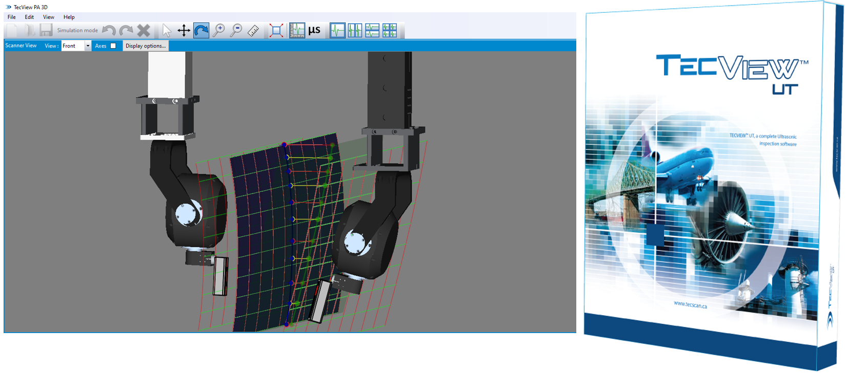
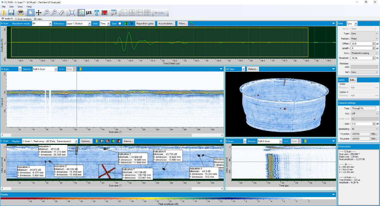
The operating software used for automated UT is an essential element that is the core of an automated scanning system. It provides inspectors with the necessary tools to define scanning trajectories and associated settings, as well as to collect and analyze the required NDT data. TecScan has developed one of the most advanced NDT software suites for automated inspection purposes using conventional ultrasonic technologies (conventional and Phased Array UT), as well as eddy current and Bond Testing technologies. Each module of TecView® contains tools that are specific to the used technology, while sharing the C-Scan image analysis tools to manage the entire material evaluation process.
One of the main challenges of an ultrasonic inspection is associated with the shape of the parts. The software must therefore first be able to generate reliable scanning trajectories that follow the part structure to maintain proper beam alignment. However, complex geometry can also be associated with variations in ultrasonic propagation properties, resulting in variations of sensitivity as a function of position on the part. Important variations in part curvature and, when doing transmission scanning, in part thickness can lead to significant differences of signal amplitude. This typically leads to a local interpretation of data, or multiple scans ran at different receiver gains to cover the entire part.
Advanced Gain Correction Map (GCM)-Patented
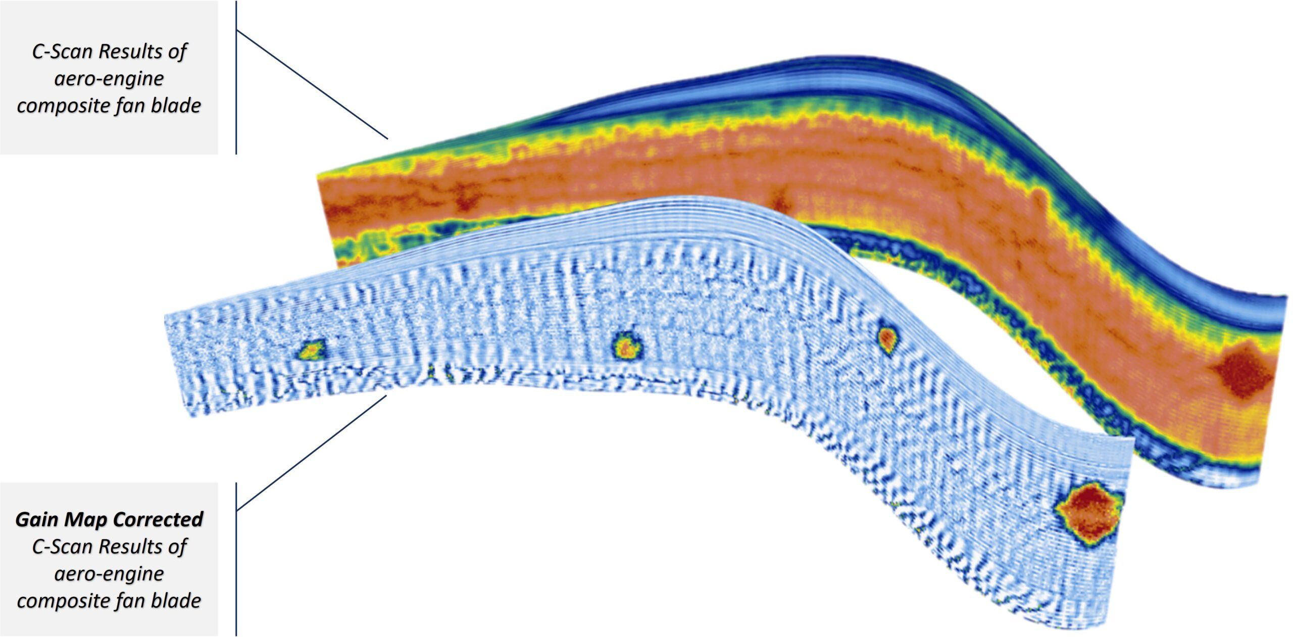
An advanced Gain Correction Gain approach was developed and patented by TecScan to automatically account for sensitivity variations in parts. While such part would typically be divided in sections of different sensitivity adjustments and/or of adapted detection thresholds, the gain correction map tool automates this process; it uses a gain variation map of the part built from the scan of one or multiple reference parts to perform these adjustments automatically.
“Once a reference gain sensitivity map has been defined, it can then be used for scanning of identical production parts by dynamically correcting the gain sensitivity as the probe moves across the part surface. In other words, calibration of sensitivity is based on the observable attenuation caused by the part’s geometry and is then automatically corrected during the scan.
For transmission scanning, this translates into a more uniform amplitude of the transmission signal across the part surface. Analysis such as dB drop sizing becomes much easier since the amplitude reference is the same across the entire part instead of having to do local analysis. This leads to a data set that is much easier to interpret, while providing optimal signal-to-noise ratio at any position on the part.
Some Results to Share…
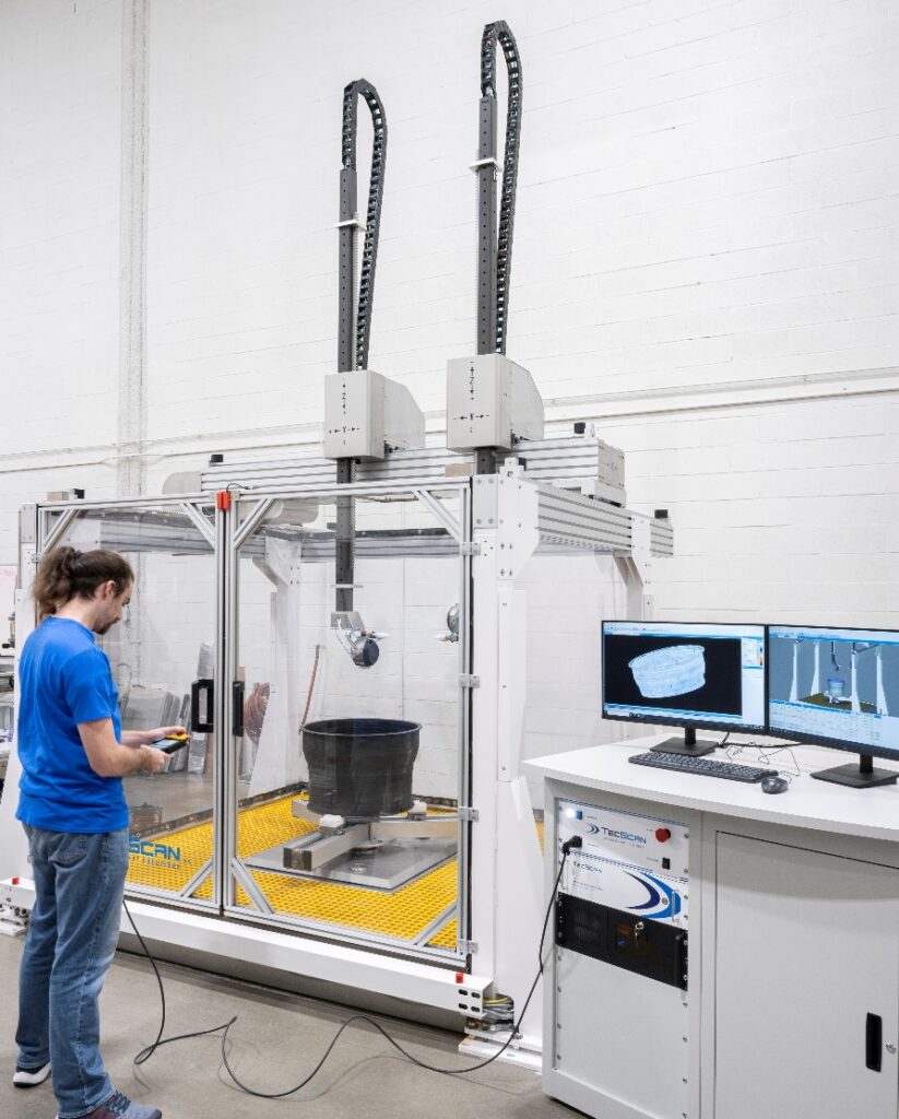
The following application represents automated inspection of a composite fan case using the URSUS-500 gantry ultrasonic scanner. This part was inspected in transmission using a pair of water squirter nozzles with the probes covering a portion of the barrel and the FWD flange areas.
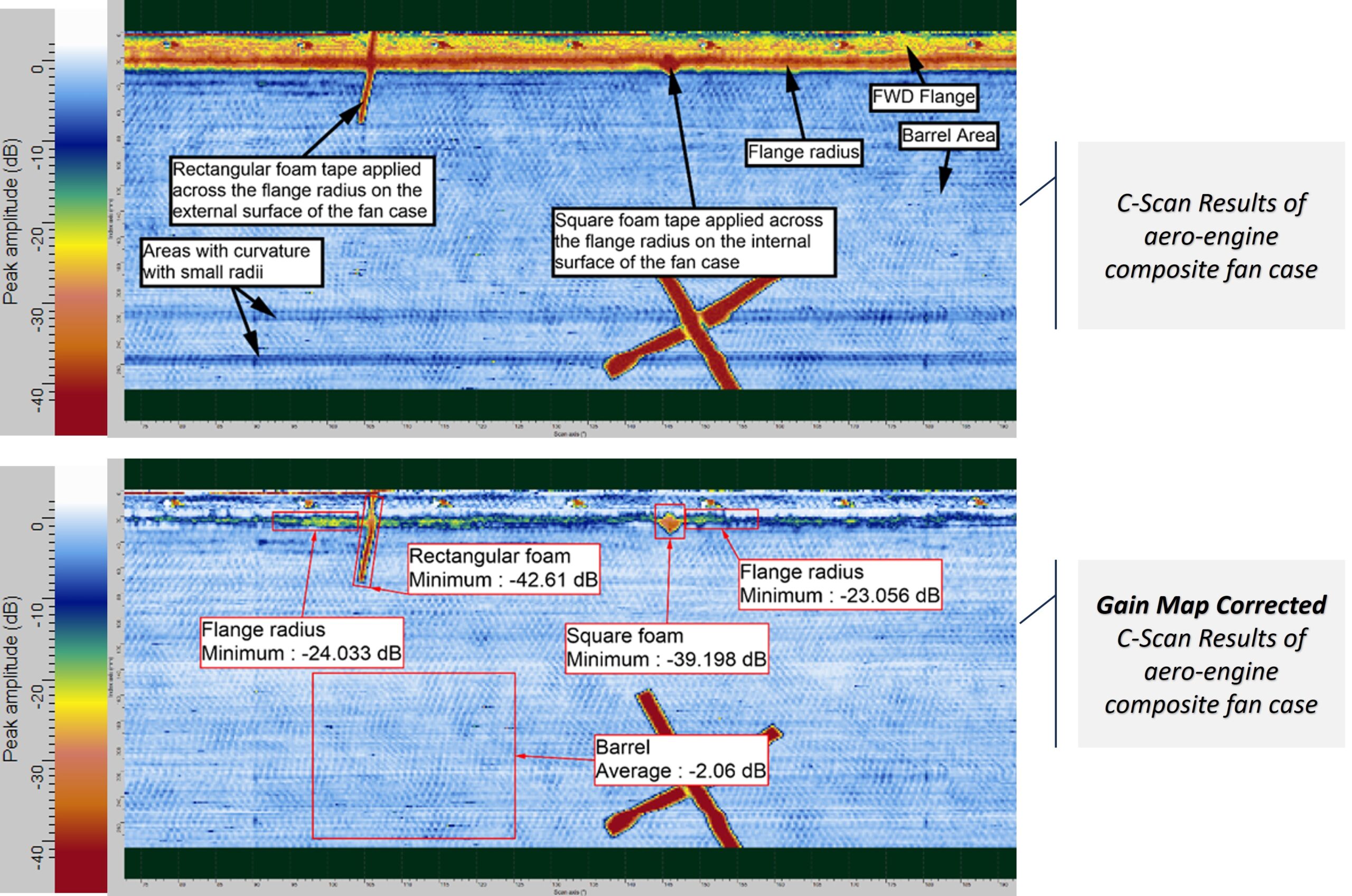
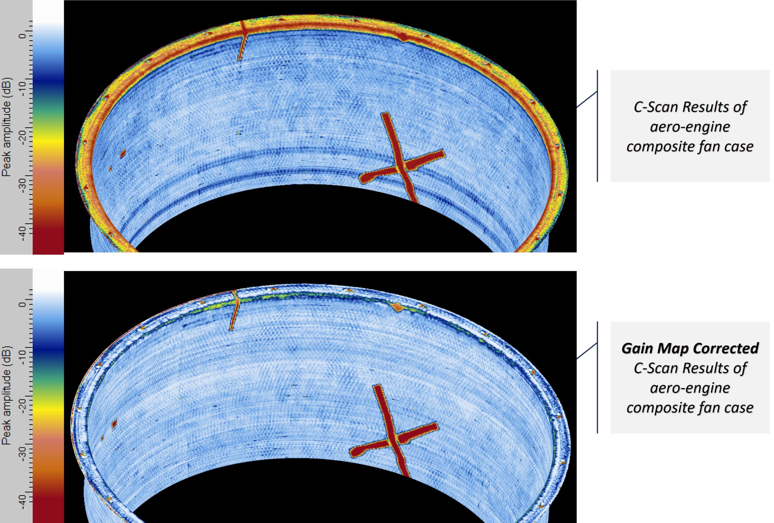
Due to the geometry of the flange and the physical dimensions of the probe/nozzle assembly, transmission across the flange and flange radius cannot be achieved at an optimal probe angle. For this reason, the ultrasonic signal drops significantly around the flange radius and falls below the noise baseline in the radius itself, as illustrated in the following figure.
In this example, variations in thickness of the barrel area did not have a significant impact on the amplitude of the transmitted signal, however the presence of curvatures of small radius did result in visible drops of signal at the bottom of the C-Scan.
Since this fan case has a cylindrical symmetry, a simple axial gain sensitivity map was acquired as a refence; drops caused by repeatable geometrical features of the part are expected to be the same from one part to another if they ate manufactured in a repeatable way. The part was rescanned with this GCM (gain correction map), which means that the software dynamically changed the gain setting on the ultrasonic unit as the scan progressed. This resulted in a C-Scan image with a normalized background, revealing indications with an optimal signal-to-noise ratio, especially in areas of higher signal attenuation.
Building a scanning system with proper mechanical accuracies and repeatability is key to use of such advanced functionality. It is the reproducibility of the overall setup that allows to physically match a reference to production parts.


