

Ultrasonic Immersion Testing: Essential Tools for Automated Inspecting Aircraft Engine Disks and Circular Components
AUTOMATED UT SYSTEMS
The aviation industry is subject to many strict standards in terms of quality assurance and inspection of components and structures. Components that experience high levels of stress and environmental hazards should be cleared of any defects that would cause any potential failure. As such, TecScan’s Automated Ultrasonic Testing (UT) Systems enhance the UT scanning precision of structures and components with complex geometries. In the case of aeroengine disks and circular aircrafts components, these automated UT systems simplify the scanning process by providing the appropriate scanning hardware and software tools. This effectively minimizes human error in handling during inspection and in identifying potential defects, as well as optimizing inspection and scan times. Such automated UT Systems are usually equipped with turntable (TT) assembly and Advanced 3D Software to precisely perform automated UT scans of aero-engine Circular Components.
EXPERIMENTAL SETUP: AUTOMATED UT IMMERSION TANK
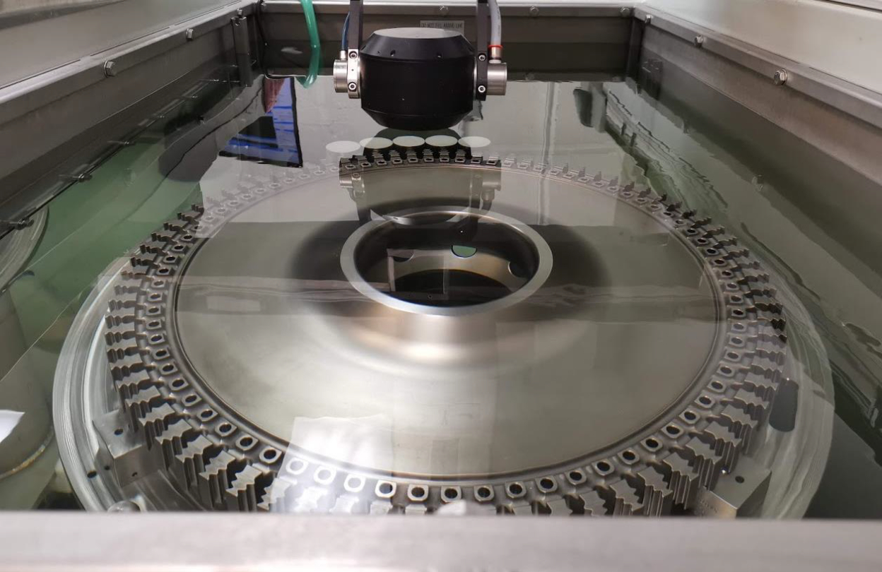
To illustrate the Immersion Ultrasonic Testing of Circular Components, tests were performed using a multi-axis Automated UT immersion tank system equipped with a high precision Gimbal/Gimbal manipulator and turn table (TT) assembly. The UT experiments were performed on two aero-engine samples containing actual defects using a 15 MHz transducer. The first sample represents a welded engine seal panel, whereas the second sample is a pre-machined aeroengine disk. On the welded engine seal panel sample, advanced 3D Scan mode was used in pulse-echo configuration to perform automated UT testing. On the pre-machined disk sample, Continuous Rotational Scan mode was used to perform UT scan, rotating the turntable while indexing linearly along the disk radius.
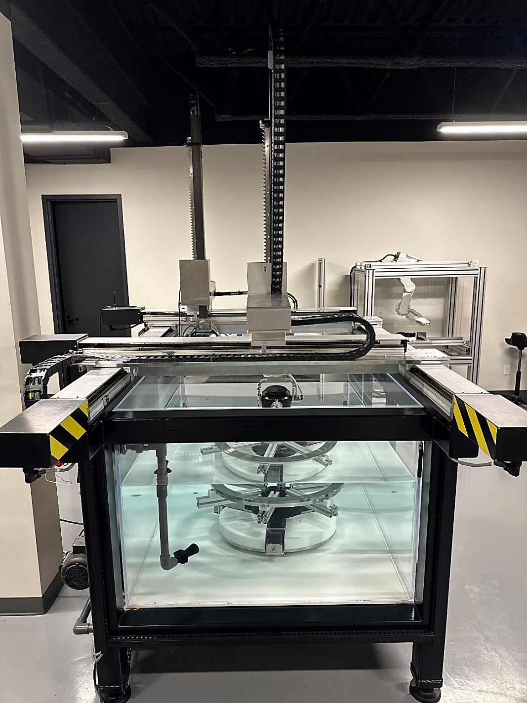
FIGURE 1. MULTI-AXIS ULTRASONIC IMMERSION SYSTEM
TecView® 3D is used to control the scanner motion and perform the 3D automated inspection. In this case, the software enables inspectors to either import a model of the parts to be scanned, or define its radial profile, simulating the overall scanning process to ensure probe orientation and optimized ultrasonic signal quality for accurate defect detection and sizing.
AUTOMATED C-SCAN TEST RESULTS: WELDED SEAL PANEL SAMPLE
To perform this inspection, 3D Rotational Scan mode is selected in TecView® software. First the seal panel sample is centered on the turntable and a contour profile is created by the user to perform the automated pulse-echo inspection. TecView® then generates the part surface by extruding the created profile in 360 degrees around the turn table rotation axis. Figure 2 illustrates the welded seal panel part surface and its contour profile view.
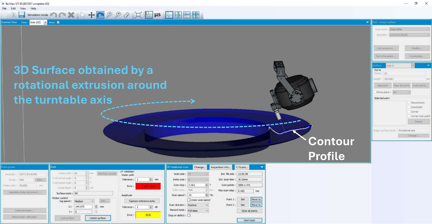 FIGURE 2. CAD REPRESENTATION OF A SEAL PANEL IN TECVIEW® 3D
After completing the scan, TecView’s Annotation Module provide the necessary tools for automatic defect detection, sizing and reporting. The 3D representation of the part and the ability to move the scanner to an area from the completed C-Scans enhance the understanding of the part’s properties.
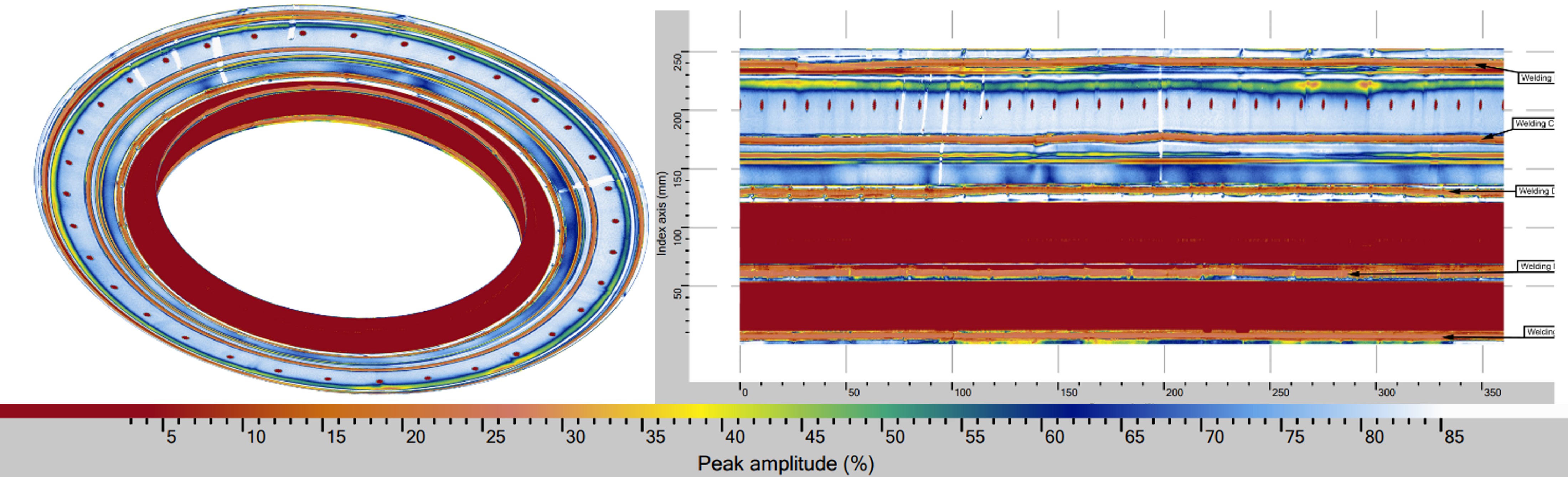 FIGURE 3. 3D AND RECTANGULAR C-SCAN IMAGES OF THE WELD INTERFACE OF A WELDED SEAL PANEL
AUTOMATED C-SCAN TEST RESULTS: PRE-MACHINED DISK SAMPLE
To perform this inspection in 2D configuration, Continuous Rotational Scan mode is selected in TecView® software. First the radius of the circular part is input in the software to make sure that the spatial sampling and the sizing of defects meets with inspection industry standards. Then a simple 2D scan is performed by continuously rotating the turntable while indexing along its radius. The generated Cartesian C-Scan result is converted to a Polar C-Scan, providing better and more intuitive top view scan representation of the part. This makes it easier to output defects positions on the inspected part in terms of radial distance and angular position from a landmark (e.g. marking on the inner or outer diameter).
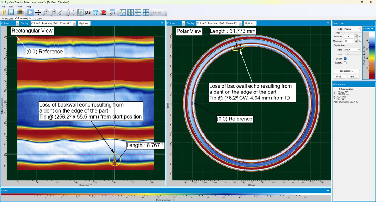 FIGURE 4. EXAMPLE OF RECTANGULAR VS POLAR C-SCAN IMAGE DISPLAY FROM THE SCAN RESULTS OF A PRE-MACHINED ENGINE DISK WITH A LARGE DENT ON ONE OF ITS EDGES
CONCLUSIONS
In effect, TecScan’s Automated UT Inspection Systems significantly enhance the precision and efficiency of aircraft engine disks and circular parts. By automating the scanning process and providing advanced tools for defect detection and analysis, these systems ensure high-quality assurance and compliance with stringent industry standards.
This NDT technology not only reduces human error but also optimizes inspection times, making it an invaluable asset in the aviation industry.
Related Content
TecView® 3D
Advanced NDT Systems: Scan3D®


