Automated UT Systems Calibration: The quest for perfect 3D scanning repeatability
Automated UT Systems require precise and thorough mechanical calibration to achieve a high degree of scanning accuracy, repeatability and stability. The versatility of these systems enables users to utilize different UT probes for various non-destructive testing applications. Due to minor imperfections of the probes’ active element alignment, the identification of the true center from which ultrasonic waves are emitted becomes critical for scanning parts with complex geometries in 3D or contour following. Not taking this into account introduces some errors in the interpretation of the 3D positioning which could compounds during inspections, leading to scale offsets and erroneous measurements.
Automated UT Calibration
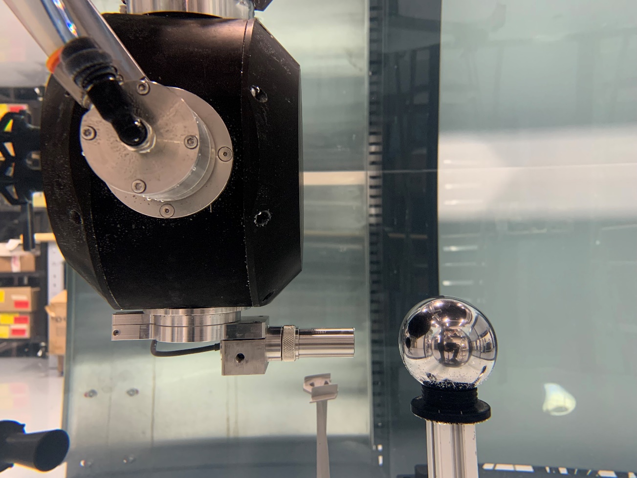
The calibration method must be such as it follows a simple, repeatable protocol to minimize operator variability. As such, a spherical stainless-steel ball with sufficient dimensional accuracies is used. The process consists of maximizing the UT signal on the ball at different points and comparing the perceived values with the known values of the ball’s dimensions. Doing so reveals the offsets that need to be input on the X-Y-Z axes to align the Tool Center Point (TCP) of the probe. A validation can be made by locking the probe on the center of the ball and verifying that the UT signal and water path are stable.
The risks of not calibrating the probe assembly position impact both the setups before the automated scan and the C-Scan results afterwards. When positioning the 3D model of the part to scan, the system tries to match the user’s measured cloud of points with its 3D model. Having an offset on the TCP makes it so that the dimensions of the point cloud will never match the 3D model, making it possible to sometimes have a fit only on one area of the part and the whole fit virtually impossible. The resulting automated UT scans will have drops in signal amplitude since the ultrasonic beam hits the part at the wrong incidence angle. This is particularly critical when inspecting metallic materials, using high frequency probes, or when inspecting parts with small curvature radii. which are all cases where small errors in incidence angle can have an important impact on the ultrasonic signal.
Scanner Calibration Test Results
To demonstrate the consequences of a good calibration of the Automated UT System, a small aero-engine turbine blade was scanned before and after calibration of the TCP of a 30 MHz transducer, the objective being to measure the thickness at key locations across the blade surface. In this example, the maximum correction applied on the TCP is a lateral shift of 0.51mm from its theoretical position.
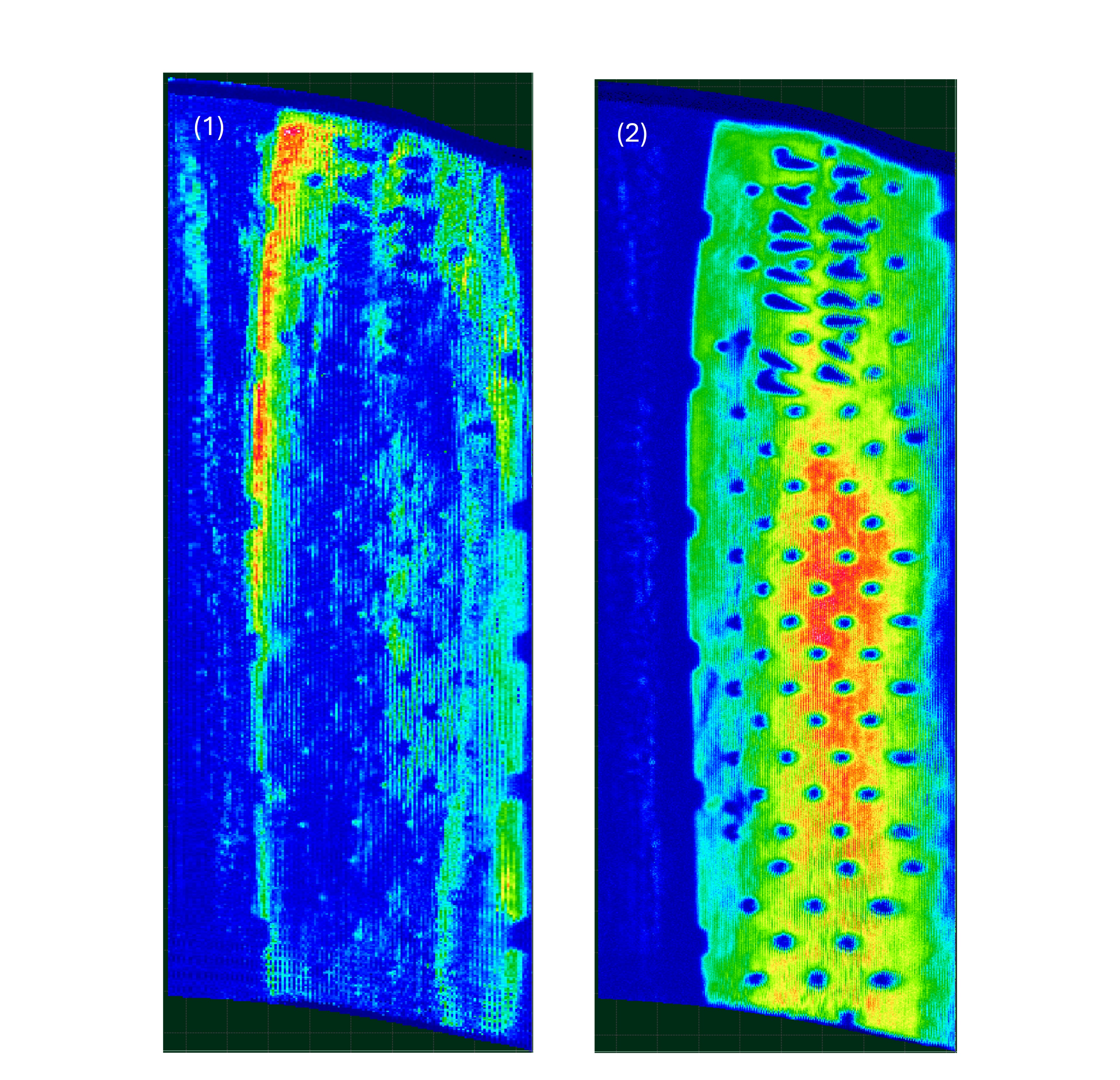
FIGURE 1: FRONT WALL SIGNAL AMPLITUDE OF TURBINE BLADE BEFORE (1) AND AFTER (2) CALIBRATION.
The calibration has a great effect on the quality of the scans for a small part, especially when scanned at high frequency. When inspecting components such as the blade of this example, the tolerance in terms of thickness is relatively strict, mainly for aerospace component testing.
Proper calibration of the TCP has a direct impact on the UT angle of incidence at the front wall, which in turn greatly increases the amount of ultrasonic signal that reaches and reflects from the back wall. While proper normalization of the front wall signal is the starting point of any automated ultrasonic immersion scan, achieving this and obtaining strong backwall echoes is key to performing reliable and accurate thickness measurements.
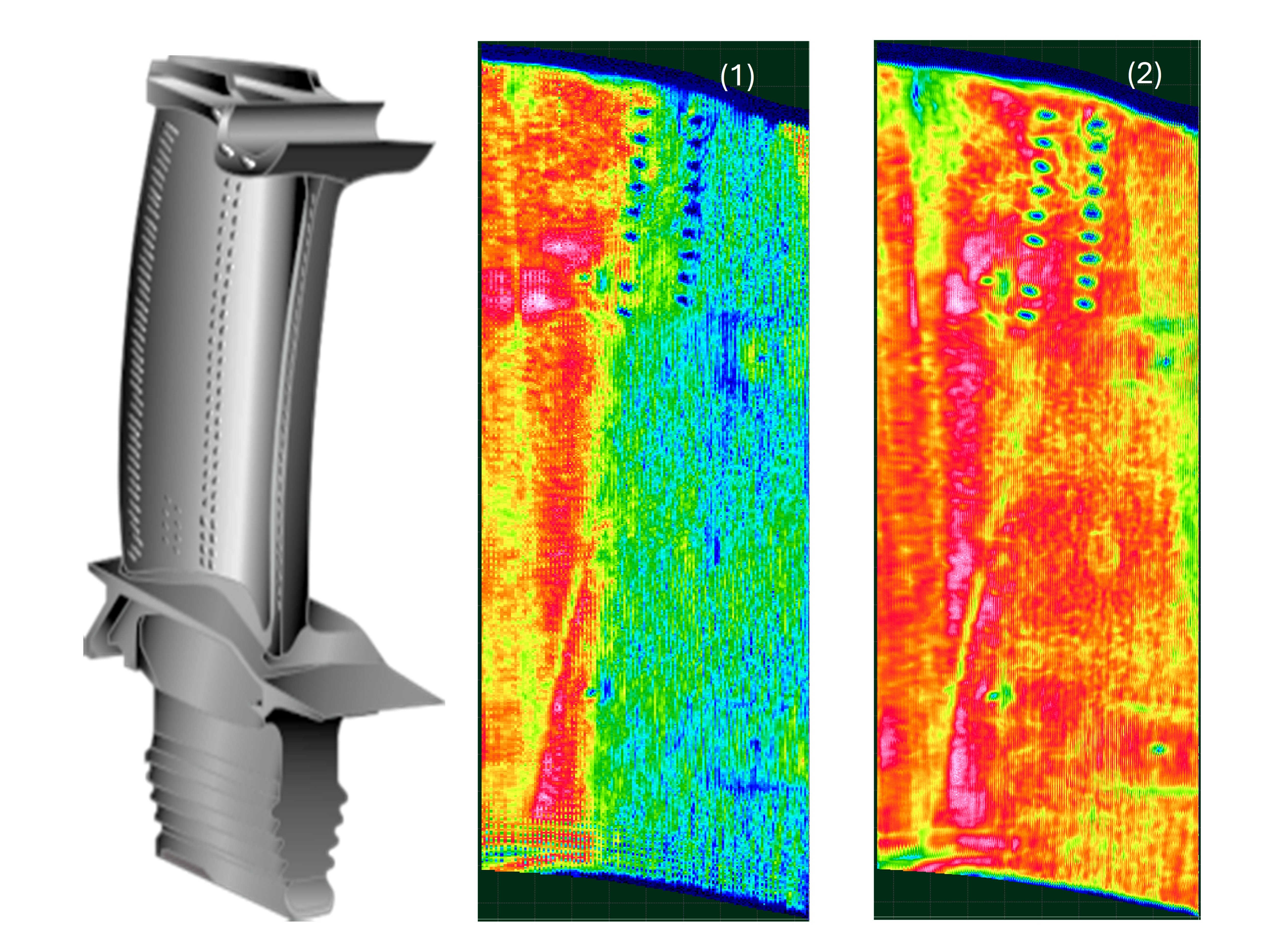
Figure 1 shows how the intensities of the front wall signals are more uniform following proper calibration of the TCP, while Figure 2 demonstrates how this consequently impacts the uniformity and amplitude of the back wall signals of the turbine blade part.
 FIGURE 2: BACK WALL SIGNAL AMPLITUDE OF TURBINE BLADE BEFORE (1) AND AFTER (2) CALIBRATION.
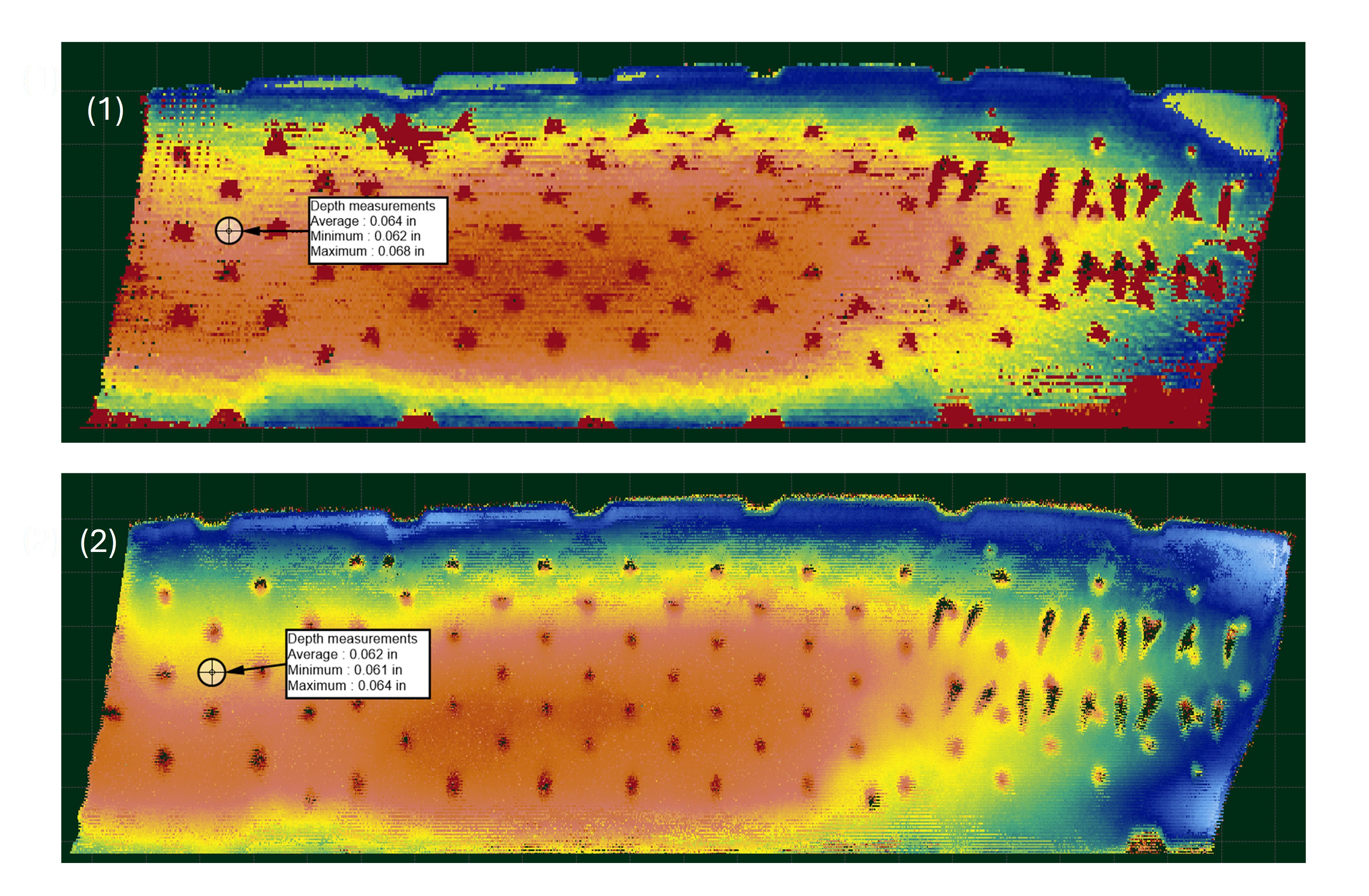
As a result, Figure 3 shows the C-Scan thickness map before and after calibration. When compared to the calibrated result, the uncalibrated scan presents variations in thickness readings that could lead to errors in the conformity analysis of such part.
FIGURE 3: THICKNESS MEASUREMENTS OF TURBINE BLADE BEFORE (1) AND AFTER (2) CALIBRATION.
In effect, the calibration method for TecScan’s Automated UT Systems is a simple protocol that enables precise, stable and repeatable 3D complex scans and measurements.


