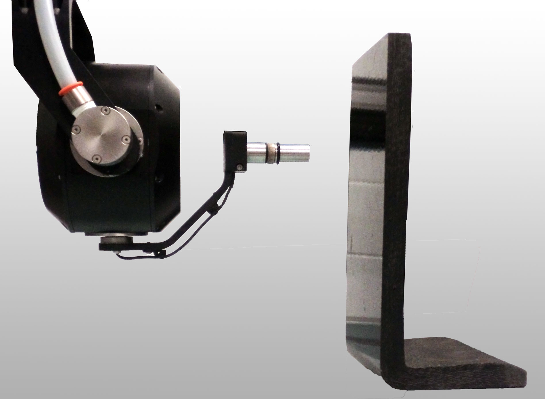
Automated Ultrasonic Testing: Transducer Squint Angle Correction
Ultrasonic Testing technique uses ultrasonic transducers to perform non-destructive manual and automated testing. Such transducers are typically designed to generate a sound beam at a specific angle with regards to the transducer casing. For immersion transducers, the ultrasonic beam generated by the transducer element is expected to be centered on the main axis of the transducer. In practice, it is almost impossible to build a transducer with a perfectly aligned sound beam; the angular deviation of the beam with regards to the expected direction is called the Squint angle. This angle represents one of the many characteristics of ultrasonic transducers.
According to the European standard for transducer evaluation (EN 12668-2), the squint angle of a transducer must be below 2 degrees in order to meet the code requirements. Now let’s assume that a probe has a high, yet acceptable squint angle of 1.8 degrees. If it is used to inspect an aluminum part (c = 6.15 mm/µs) in water (c = 1.48 mm/µs) and the probe is mechanically set to aim the part at an angle of 0 degrees, then the angle of the ultrasonic beam will be 1.8 degrees. Based on Snell’s refraction principle, this means that the waves will propagate at an angle of 7.5 degrees below the surface of the aluminum material. As a result, a simple task such as measuring the thickness of a material becomes extremely erratic. It is therefore current practice for ultrasonic testing to correct for the squint angle in order to emit the ultrasonic beam at the correct angle.
- Transducer squint angle
- Squint angle in material
Automated Ultrasonic Testing
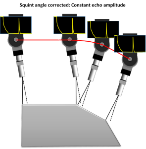
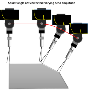
Automated Ultrasonic Testing requires a precise 0 degrees alignment of the ultrasonic beam to the desired point of incidence / point of inspection. Therefore, to control the transducer angle, we must correct for the squint angle and for possible transducer casing misalignment. Regardless of the source of deviation, the squint angle must be taken into consideration when performing ultrasonic testing. Failing to correct for the squint angle leads to unpredictable beam angle inside the test piece.
- Transducer squint angle (corrected)
- Transducer squint angle (uncorrected)
Squint angle correction
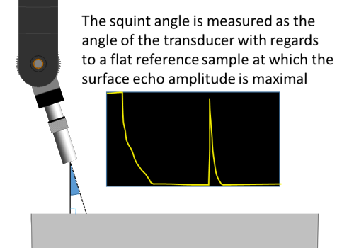
When performing ultrasonic testing of flat samples in pulse-echo, the squint angle is simply corrected by optimizing/varying the transducer’s angle to maximize the amplitude of echo signals. Optimizing the amplitude of the echo signals guarantees the normality of the ultrasonic beam with the entry surface. However, such a correction is more challenging when performing automated ultrasonic testing of parts with complex geometries where transducer contour-following and 3D scans are required. In this case, it is the movement of all axes that must be corrected in order to ensure the proper ultrasonic beam entry angle.
In order to perform squint angle correction, pulse-echo measurements are performed on a flat calibrated reference to evaluate the direction of the central axis of the sound beam. The directivity of the ultrasonic beam is measured by comparing the angle of the transducer with the known angle of the reference sample. The obtained value is then input to the 3D contour following software (TecView™ 3D), which can calculate axes displacement paths that ensure a constant and optimal ultrasonic beam entry angle along the surface of the tested part.


