Embracing Virtual Inspection Tools with TecView® 3D for Automated Ultrasonic Testing of Aerospace Components
Embracing Virtual Tools Inspection with TecView® 3D
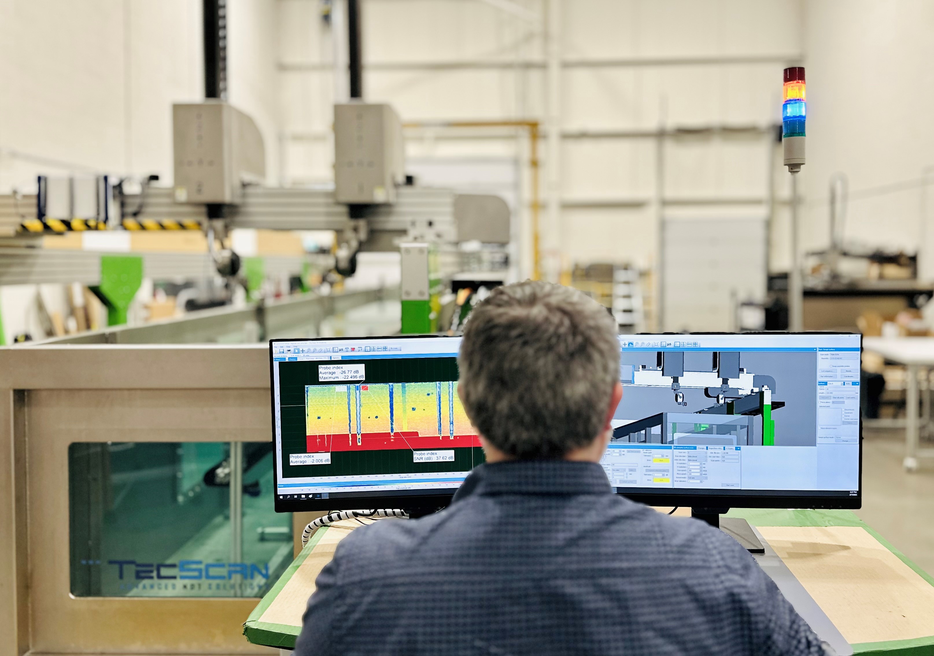
TecView® 3D introduces a virtual environment that mirrors the physical inspection setup, allowing operators to simulate and plan ultrasonic testing processes with unprecedented precision. By integrating CAD models of both the inspection system and the component under examination, TecView® 3D enables:
- Accurate Path Planning: Operators can define and visualize scan paths over complex geometries, ensuring comprehensive coverage and optimal probe alignment.
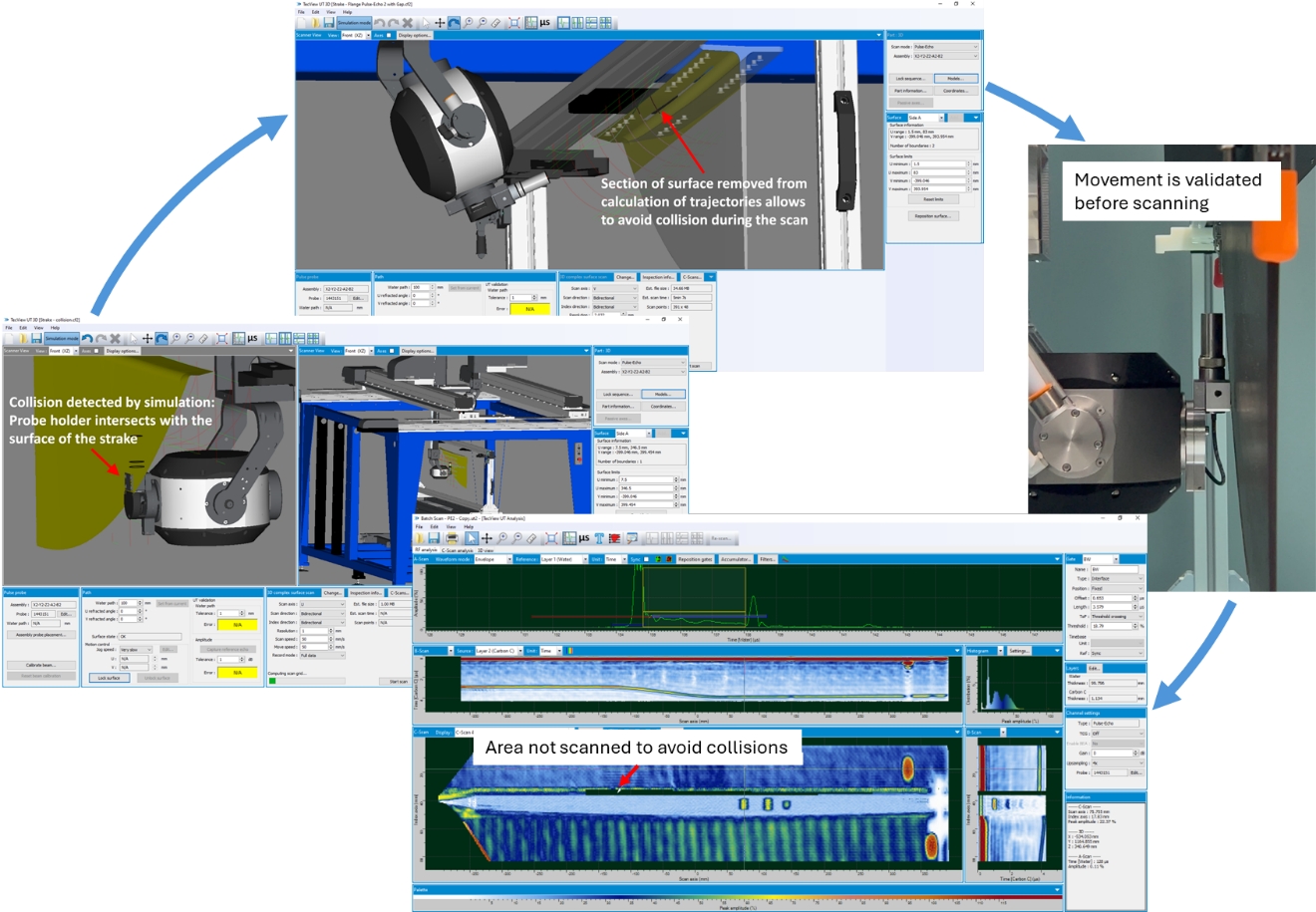
- Collision Detection: The virtual environment facilitates early identification of potential interferences between the scanner and the part, mitigating risks before actual inspection.
- Enhanced Training: New personnel can familiarize themselves with inspection procedures in a risk-free virtual setting, accelerating the learning curve and reducing on-the-job errors.
Fig. 1. Illustration of the preparation of a scan plan, from simulation and removal of problematic areas in the virtual environment, to the validation and scanning of the part.
Key Features Tailored for Aerospace Applications
Aerospace components often feature complex shapes and materials, posing challenges for standard inspection techniques. TecView® 3D addresses these challenges with features such as:
- 3D Contour Following: The software’s contour-following capability allows for automated scanning of parts with intricate curvatures, maintaining consistent probe orientation and distance to ensure reliable data acquisition.
- Teach and Learn Functionality: Operators can “teach” the system the geometry of a specimen through an interactive process, enabling the software to “learn” and replicate the inspection on similar parts, thereby streamlining repetitive inspections.
- Real-Time Data Visualization: TecView® 3D provides immediate feedback during inspections, displaying real-time A and C-Scan images, which are crucial for detecting subsurface anomalies in critical aerospace components.
- Production Oriented Tools: Loading of scan setup files and data logging based on barcodes, software management of scan data files name and recording location, as well as automatically filled inspection reports all contribute to increased productivity.
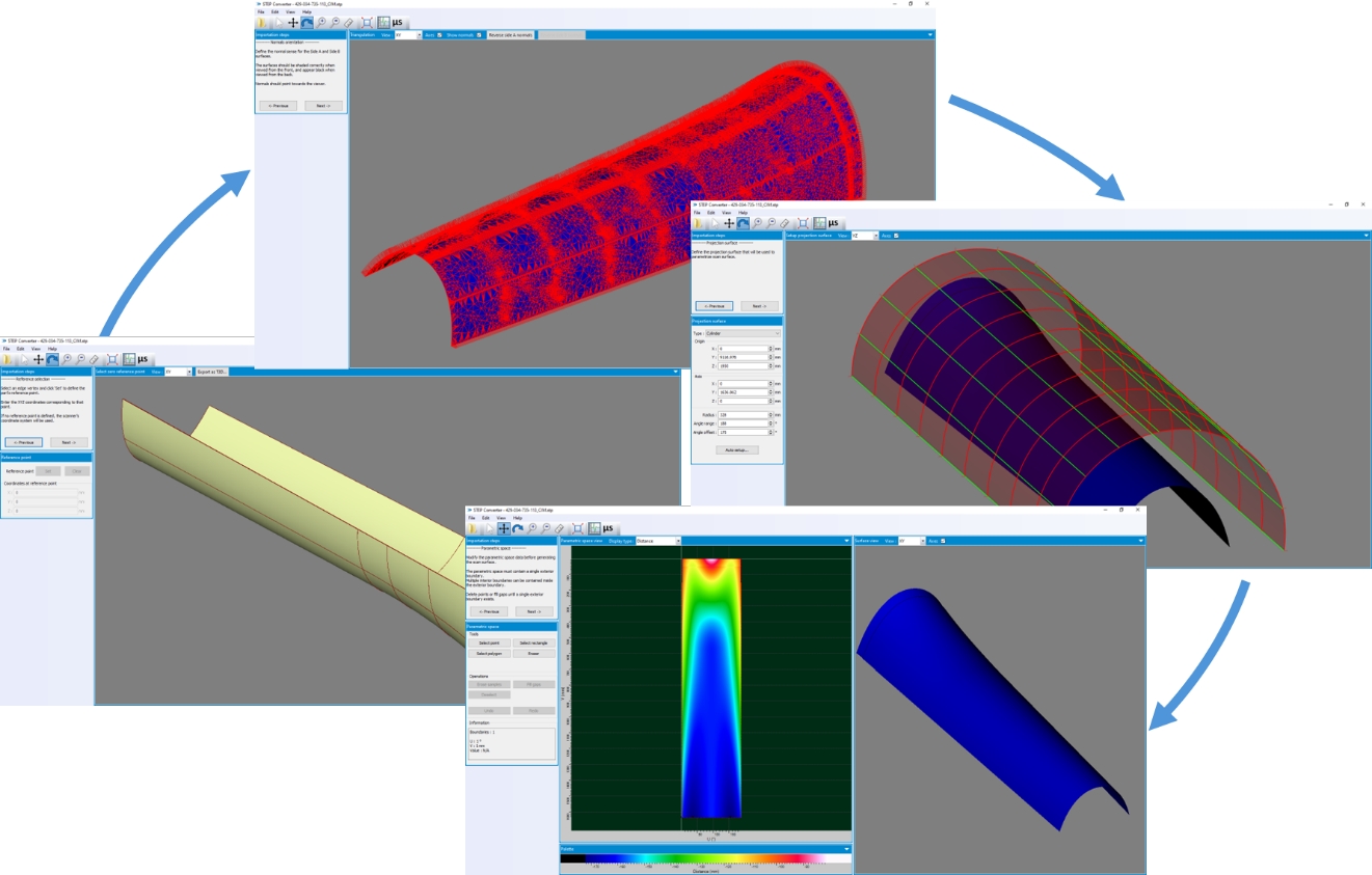
Fig. 2. From CAD to scan trajectories: TecView® 3D converts CAD to axes trajectories from simple steps.
Advancing Aerospace NDT Practices
By integrating TecView® 3D with its virtual inspection tools into their NDT workflows, aerospace manufacturers and maintenance teams can achieve:
- Increased Inspection Efficiency: Virtual planning reduces setup times and optimizes scan sequences, leading to faster inspections without compromising accuracy.
- Improved Detection Capabilities: Advanced imaging and analysis tools enhance the detection of defects such as cracks, voids, and delaminations, which are critical for ensuring flight safety.
- Cost Savings: Early detection of potential issues and the ability to simulate inspections virtually can significantly reduce the need for costly rework and material waste.
In conclusion, TecScan’s TecView® 3D stands at the forefront of NDT innovation, offering aerospace professionals a powerful tool to navigate the complexities of modern aircraft component inspection. By embracing this virtual environment, the industry can ensure higher quality standards, enhance safety, and drive efficiency in inspection processes.


