TecView® UT: Variable Inspection Gating Tools for Ultrasonic C-Scan Imaging of Aero-engine Components
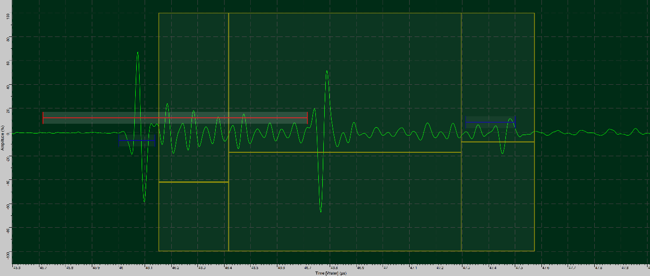
Gating of ultrasonic signals represents an essential tool when performing Automated Ultrasonic Testing (UT). Signal peak follower gates are the first ones to be defined and they are used to synchronize the other gates position with the time displacement of the reference signal echoes. Gates can also be used to detect the interface echo between two materials for thickness measurements. They are also used to detect echoes with the purpose of triggering detection alarms, or simply to define an area of interest to produce C-Scan images. When a gate is set, it typically captures all the ultrasound echoes within its limits and extracts a value that will be used to generate the C-Scan image (the echo maximum amplitude, time-of-flight or any other valuable information).
The extracted value by the gate will determine the color code of the associated pixel in the C-Scan image.
Don’t Lose Your Valuable Echoes
Aero-engine components such as composite fan blades/ cases or engine discs and spools, often have complex geometries, multiple layers, or both. Covering a zone of interest (internal structure or backwall echo) with a fixed gate can be challenging and may therefore require multiple setups when the thickness of the part or layers vary; in that case, the gate will only apply properly to a limited section of the part and may capture undesired echoes from outside the interest zone, or miss valuable echoes if the gate does not cover a sufficient depth range.
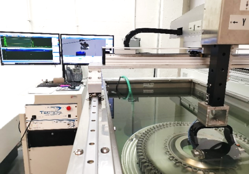
Ultrasonic Testing of Engine part sample using TecScan’s TS-3000 system
Multiple gates are required in this case, each one being adapted to a limited section of the part and leading to a separate C-Scan. Analyzing the scan results of such parts is therefore tedious and time consuming.
TecView® UT Multiple gates setup
Enhance the UT Testing with Variable Gates
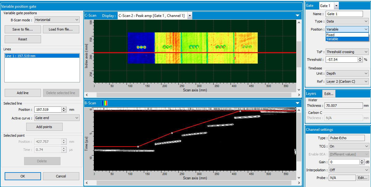
To enhance UT testing of complex parts, TecView® UT offers the option to define variable gate Position and Length. Such capability allows gates to be switched from fixed to variable settings, where their length and position can be customized according to the part profile or to a specific detection zone.
Using B-Scan views of the inspected part, gates position offset and length can be expressed as a function of position across each B-Scan. When defining gates at different scan or index position across the C-Scan, i.e. from multiple horizontal or vertical B-Scans, the software will interpolate between B-Scans to vary the gates progressively across the C-Scan image.
Example of Variable Gate definition interface
Fixed Gates Compared to Variable Ones
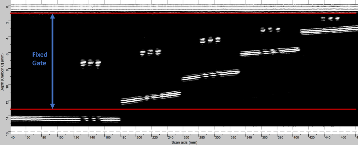
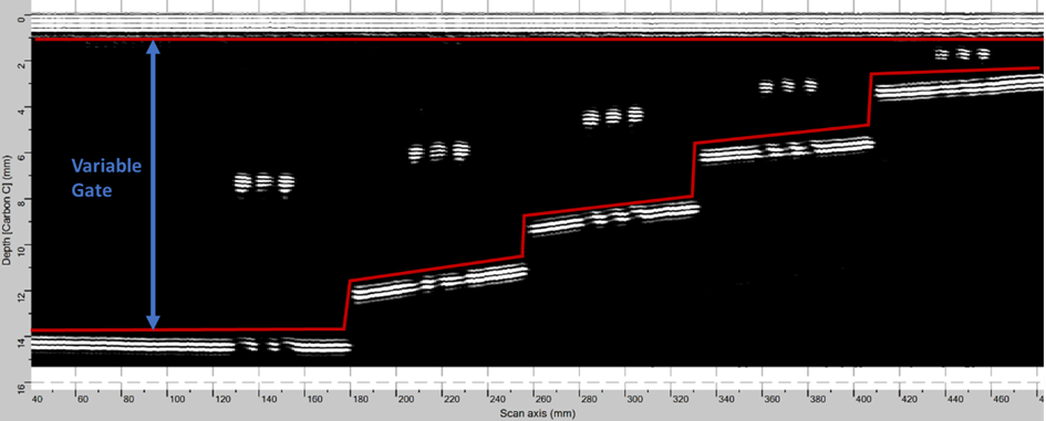
To illustrate the concept and the difference between fixed and variable gates, the same B-Scan view of an inspected part is used and shown below for both options. When selecting the Variable gate option in TecView® UT software for this example, the starting point of the gate was kept in the same position, however, the end of the gate was modified with the variable gate tool to follow the backwall echoes as shown in the horizontal B-Scan sample.
Example of a Fixed Gate (top) and a Variable Gate (bottom) defined on the same B-Scan
Variable Gates in Action
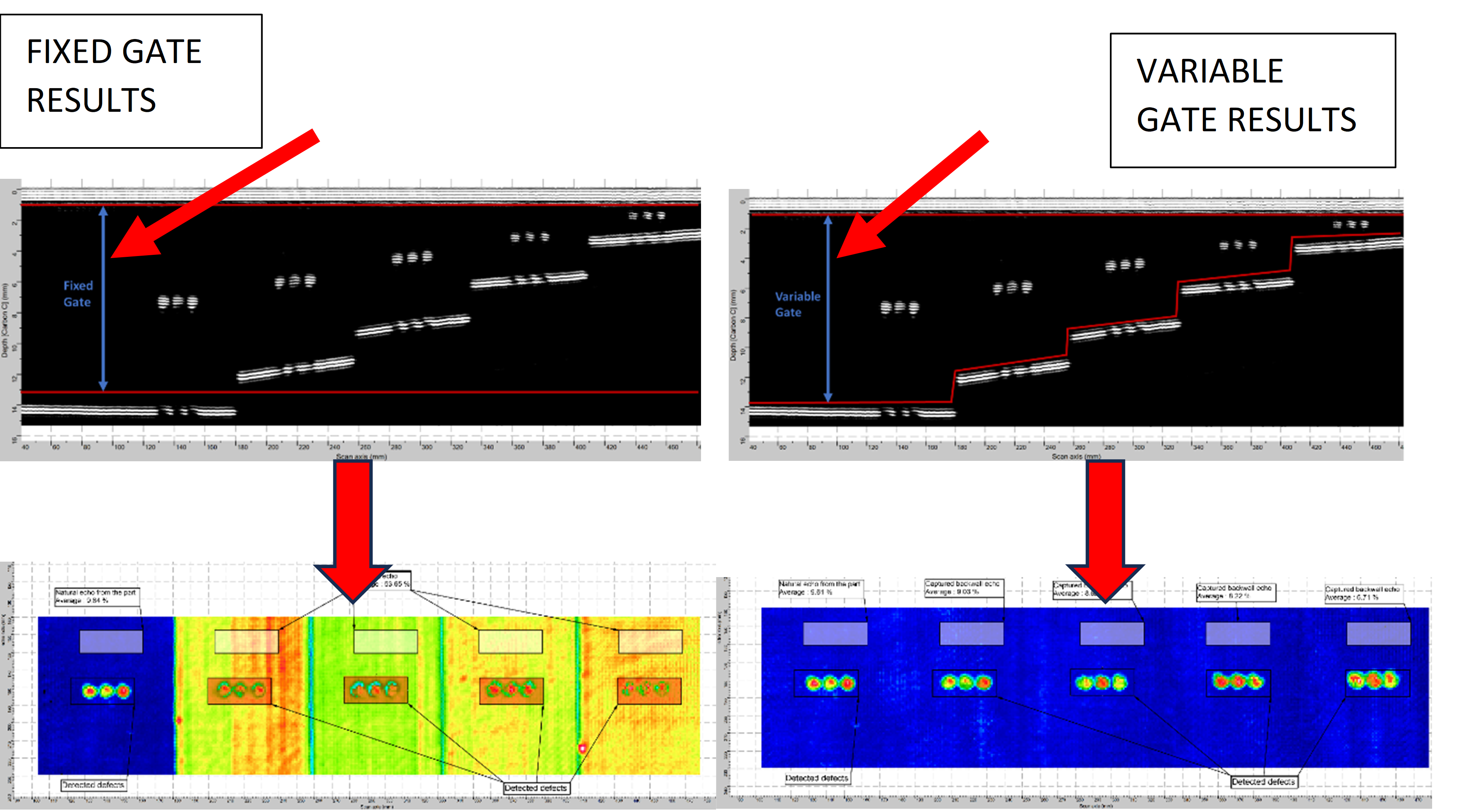
To demonstrate Variable gate applications, a stepped composite part with areas of different thicknesses and simulated defects was scanned using a TS-3000 UT immersion scanner. Fixed and Variable UT gates were consecutively applied to the scan results. The results from Fixed gate are presented on the lefthand side of the following figure, and the ones from Variable gate are presented on the righthand side.
When comparing the C-Scans of both Fixed and Variable gates, we can see all the indications from simulated defects. However, for advanced defect sizing and analysis, the C-Scan result from the Variable gate provides better signal-to-noise ratio. The signal is not mixed with the indirect backwall echoes as seen in the C-Scan of the Fixed gate setting (C-Scan on the left). In this example, indications present in the C-Scan obtained from the Fixed gate are not uniform, requiring multi-section C-Scans or multiple gates to properly evaluate the entire sample.

Schematics of the sample (Side view) illustrating the varying thickness and position of the inserts
Results with a Fixed and Variable detection gates
A Valuable Addition to your Inspection Toolbox
TecView® UT variable gate technique represents a valuable tool for advanced interpretation of UT scans, especially for applications involving parts with curved, sloped or stepped backwalls. With this gating tool, only a single C-Scan is needed to cover the entire internal structure of such complex parts. It also allows operators to optimize gate detection coverage for Alarm based detection and better C-Scan analysis by eliminating all interferences from backwall echoes.
C-Scan resulting from the variable gate illustrated on the B-Scan above


