Automated Eddy Current Circular Scanning using Linear Axes
Requirements for Eddy Current Automated Scanning
Eddy Current Testing requires a constant linear scanning speed when performing automated inspections. This is typically required because the eddy current response is a function of the applied High and Low Pass filters, whose output vary as a function of scanning speed. In general, we use mechanical turntables, which are set to accelerate to the desired constant speed. This rotational speed is then adjusted as a function of the radial position of the probe to obtain the correct linear speed. This is however not possible when performing a linear movement; speed is not constant throughout the distance traveled during acceleration and deceleration, which has a direct impact on the eddy current signals.
While this solution is presented for an eddy current inspection, it is also available for ultrasonic scanning using TecView™ UT module.
TecView™ Eddy Current Circular Scanning Mode
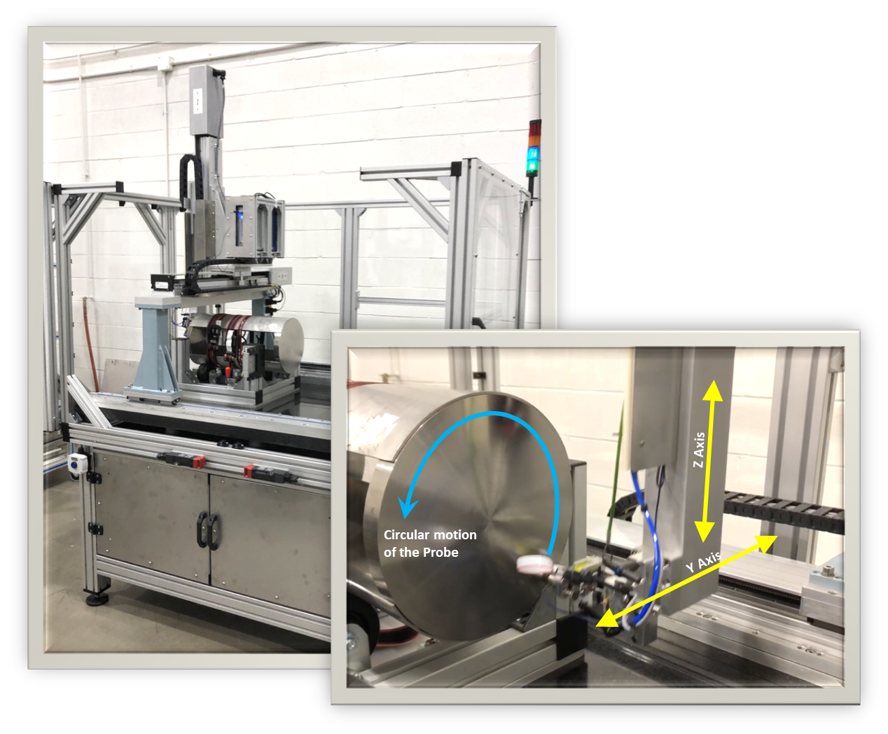
A new Circular Scanning mode was developed in TecView™ EC to perform Automated Eddy Current Testing. The developed mode uses a combination of linear axes movement to achieve a circular movement, and represents an alternative to part rotation which is not always practical due to their weight and the required part manipulation. This scanning mode can be used to perform surface scans of circular parts (e.g., disc, ring, mult, etc.), whose inspection typically requires to rotate the part while indexing the probe with a linear axis. Using the developed linear axes mode to create a circular motion, the part can remain static and only the probe is moved across its surface.
TecView™ EC Circular Scanning Mode
This section demonstrates the developed TecView™ EC Circular Scanning Mode while performing an automated inspection of a disc surface. The developed mode uses any combination of two existing linear axes of the automated scanner, e.g., X, Y, and Z axes, to generate a continuous circular motion. The maximum linear speed that can reached by a circular motion is a function of the circle diameter, as well as the linear axes maximum speed and acceleration.
When a part has a circular geometry, it is desirable to scan its surface with a circular motion instead of using a rectangular grid. This is done because it follows the natural shape of the surface, and also because it allows us to avoid the “Stop and Go” motion associated with a rectangular, raster scan; a smooth, continuous movement can be obtained from a proper circular motion control.
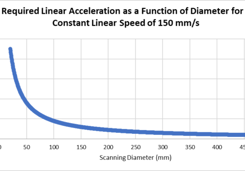
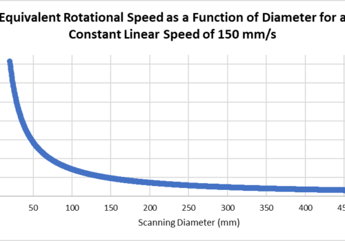
By maintaining the linear speed constant, it is the relative rotational speed between the part surface and the probe that varies as a function of diameter of the circle drawn by the circular motion. Figure 1 illustrates the equivalent rotational speed for circular motion executed at a linear speed of 150 mm/s for diameters down to 20 mm, as well as the acceleration required on the linear axes involved to maintain a constant linear speed during the circular motion.
Similar to the traditional turntable scanning mode, the rotational speed increases as the diameter of the circular motion decreases. Consequently, an area near the center of the part cannot be covered with this circular motion scan, which is not problematic for parts with a hollow bore (e.g., rings) or parts that will be bored in the center later in the manufacturing process. In the specific case of an eddy current inspection where linear scanning speed must remain constant, this is no different than scanning the part on a turntable; it does not matter if it is the probe or the part that is rotated, there is a limit in the linear speed that can be achieved when rotating around a small diameter circle in both cases.
Figure 1: Rotational speed and required linear accelerations for a circular motion scan at a constant linear speed of 150 mm/s
Circular Motion Scan Setup in TecView™
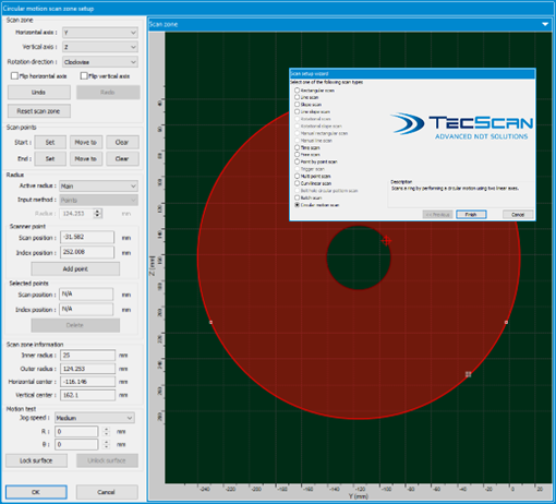
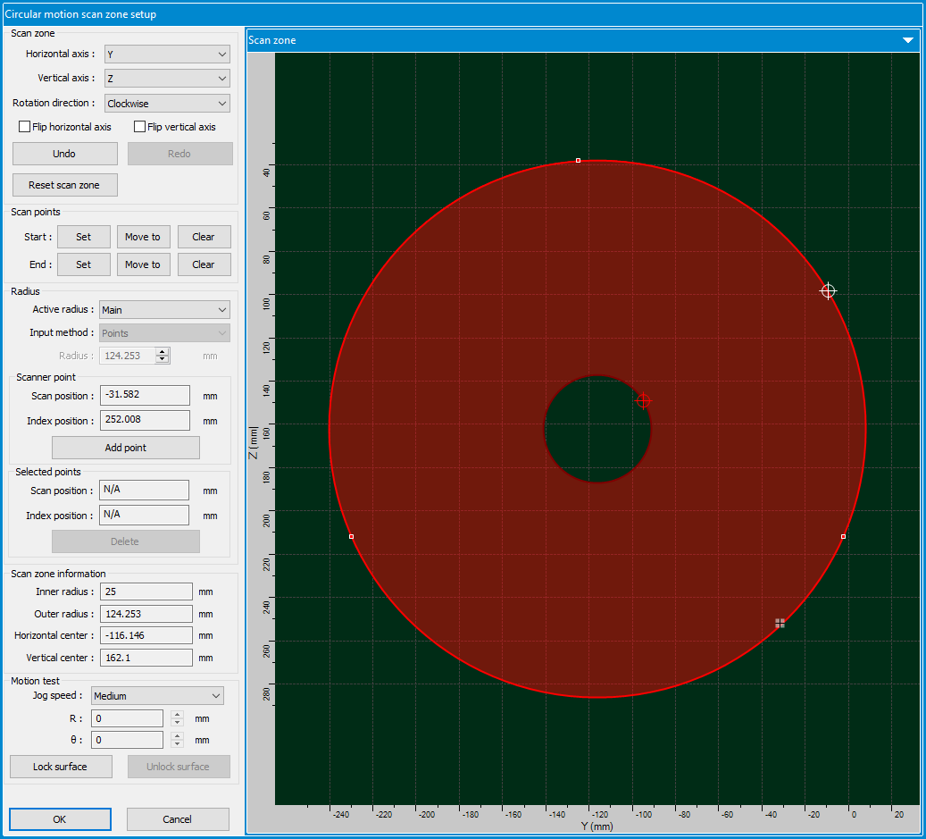
To setup circular motion scan in TecView™, we only need to define 4 points on the inspected surface:
- 3 points along the outer circumference to define the outer diameter
- 1 point along the inner diameter to define the maximum radial position
Once the inspection zone is defined and the scanner axes is locked in circular motion space, TecView™ creates and activates a virtual rotational axis. Circular scans are then achieved using motion commands similar to single axis scans.
Figure 2: Circular motion scan configuration interface
When the virtual axis is properly activated, setting up the scanner for a circular motion scan is similar to a turntable scan setup. The following figure demonstrates the scanner setup for Automated EC Circular motion inspection of disc surface.
Figure 3: Circular motion scan being performed on a disc with an Eddy Current Scanner
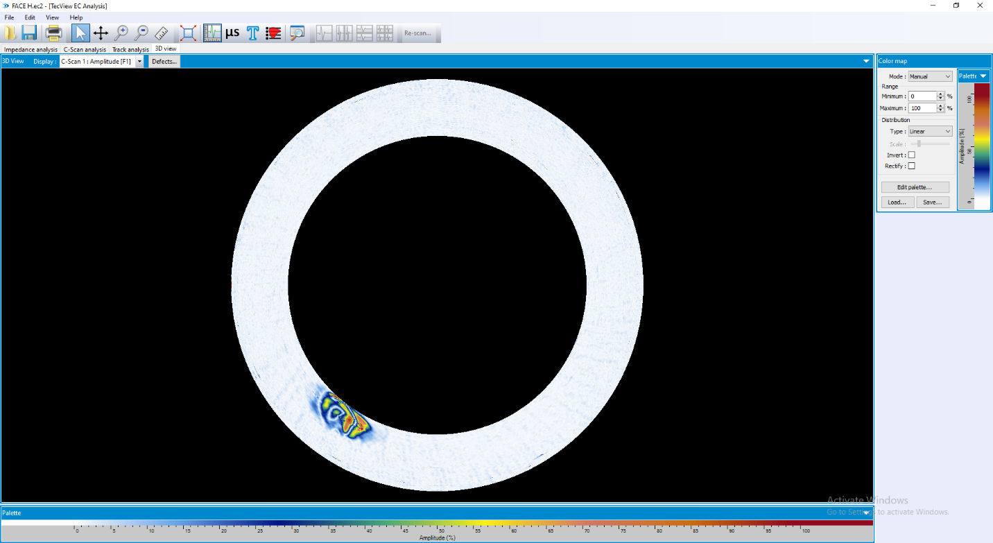
Figure 4 shows cluster indications on a C-Scan results obtained from a disc surface. The developed circular motion solution was capable of generating smooth and constant linear scanning trajectory using a combination of two linear axes.
Figure 4: Top image shows the unrolled B-Scan (rotational angle as a function of probe index), while the image at the bottom shows a reconstructed top view of the surface.
This Circular motion scan solution proved to be cost-efficient for the inspection of circular workpieces without using a physical rotational axis such as a turntable.


